Multi-channel measuring converters ЭнИ-802

1000 characters left
Обработка персональных данных включает согласие с Пользовательским соглашением и Политикой конфиденциальности и Вы принимаете их условия.

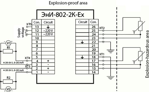
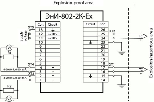
Measuring signals from resistance thermal converters, thermal couples, DC voltage, intensity and their conversion into unified current signals 0...5 mA, 0...20 mA, 4...20 mA.

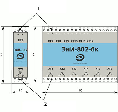
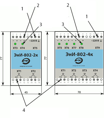
Measuring converter modifications are different from each other: number of channels (1, 2, 4, 6), input/output signal type, primary converter type, explosion protection availability, power supply unit availability.

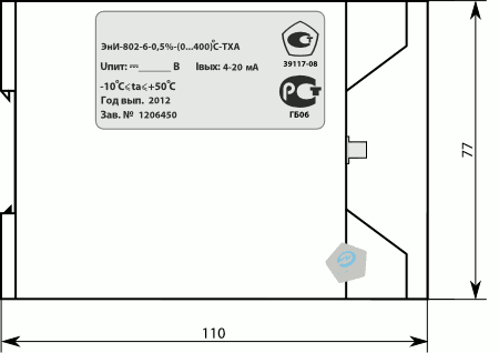
Measuring converters are manufactured for one measurement range.

  • Wide range of measured signals;
  • Low cost;
  • Up to 6 measurement channels
  • High conversion accuracy;
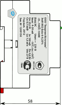
  • Two version on supply voltage: from 176 up to 264 V of A.C. Or 18 V - 36 V D.C.
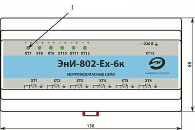
  • Explosion safety marking [Ехia]IIC or [Ехib]IIC;
  • Wall or DIN mounting options.

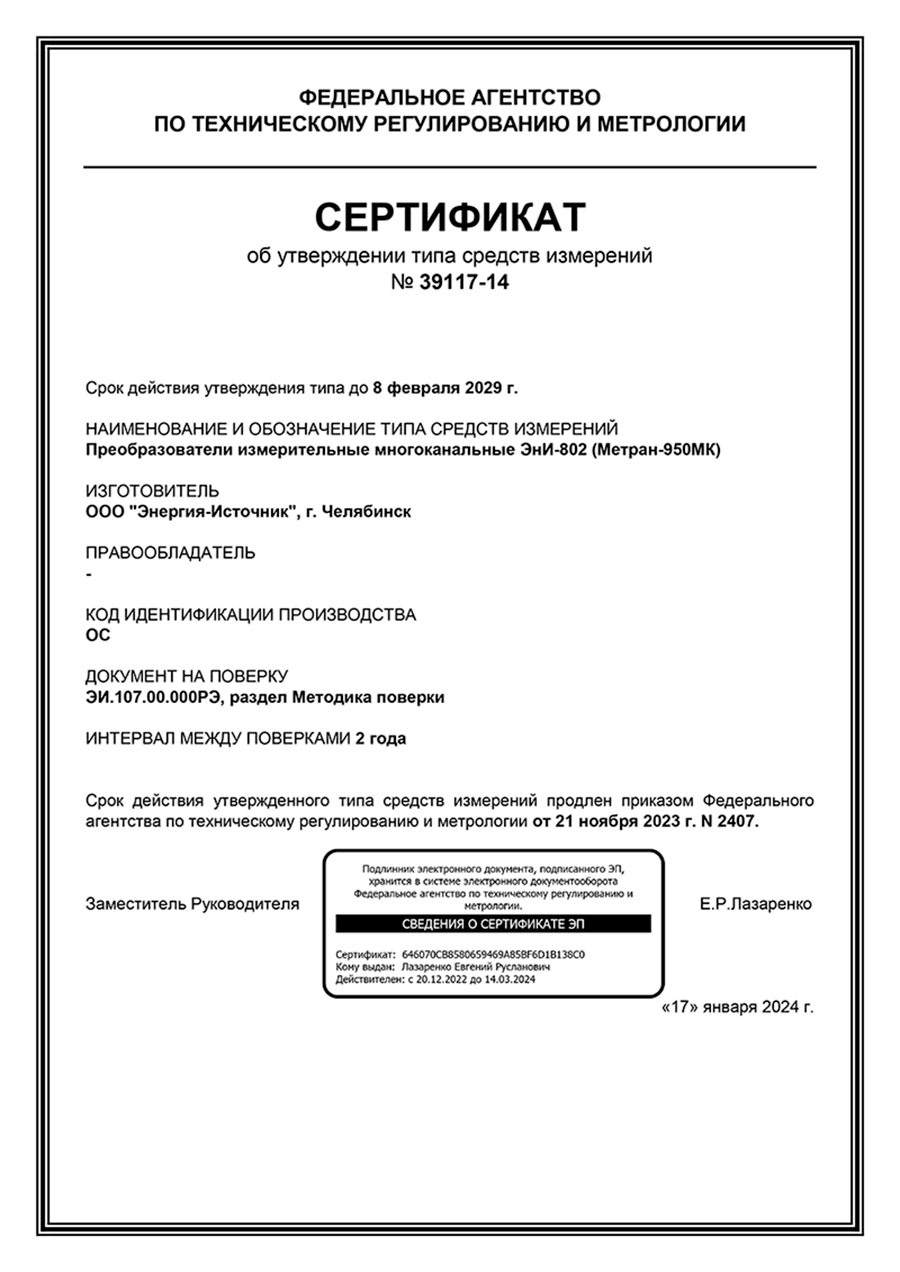
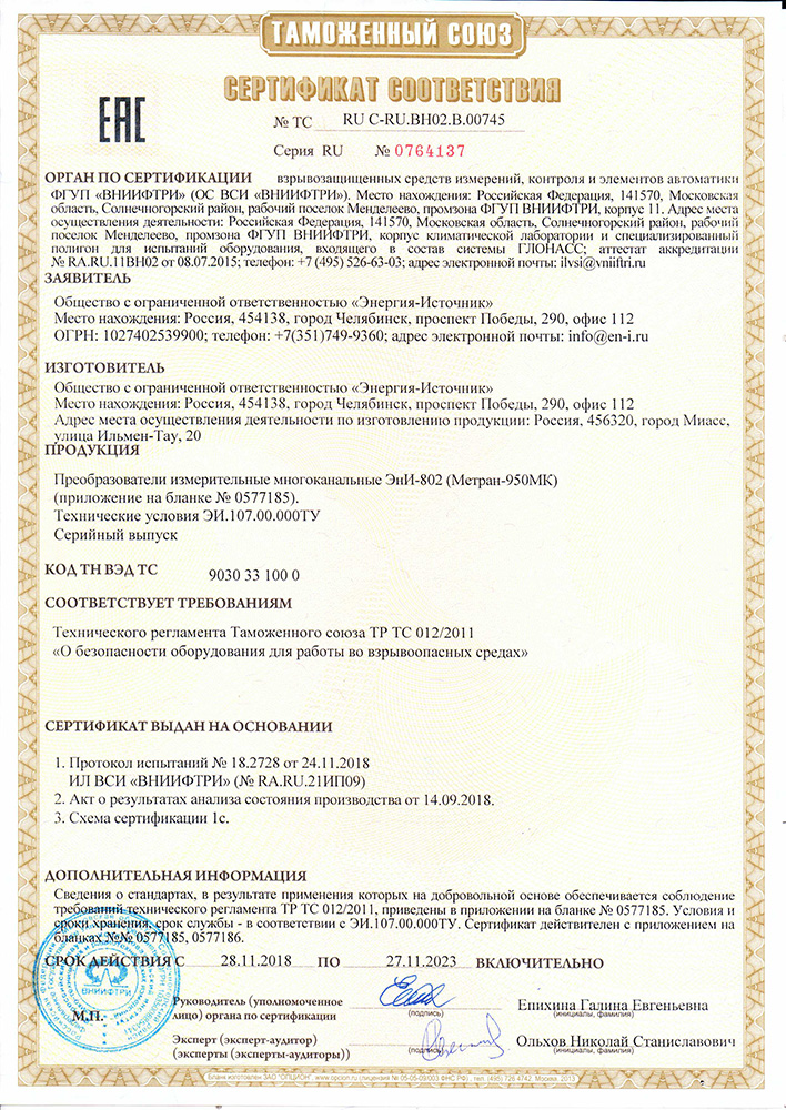
Manufactured in accordance with the technical conditions EI.107.00.000 TC

Использование Temperature

Key technical characteristics

ParameterValue
Output circuits are intended for the work with the loads, Ohm, for the signal 0...20, 4...20 mA with the account of the communication line resistance not more than 650
Output circuits are intended for the work with the loads, kiloOhm, for the signal 0...5 mA with the account of the communication line resistance not more than 2,5
Insulation strength between the input supply channel and output channels, V 1500
Structural design plastic body frame with a DIN or wall mounting option
Overall dimensions, mm 23×77×120 ЭнИ-802-Ех-1к, ЭнИ-802-1к

45×77×130 ЭнИ-802-2к (ТХА(К), ТХК(L), 100М, 100П)

70×77×130 ЭнИ-802-2к, ЭнИ-802-Ех-2к, ЭнИ-802-4к

100×77×120 ЭнИ-802-Ех-4к, ЭнИ-802-6к, ЭнИ-802-Ех-6к (ТХА(К), ТХК(L))

158×88×58 ЭнИ-802-Ех-6к

Weight, kg not more than 0,2

One-channel converter ЭнИ-802 has no a built-in power supply unit. The power supply is provided by stabilized power supply sources БП, БПМ with an output voltage 18…36 V for the general industrial purpose and 23.5…24.5 V for the explosion-proof version. The consumed power is not more than 0.72 W for general industrial purpose devices and not more than 0.48 W for the explosion-proof version.

in power supply unit is provided from the A.C. supply voltage 176...264 V with a frequency 49...51 Hz. Consumed power of two channels is not more than 3.5 VA. The power supply of the converter without a built-in power supply unit is provided by stabilized power supply sources BP, BPM with an output voltage 18…36 V for the general industrial purpose and 23.5…24.5 V for the explosion-proof version. The consumed power is not more than 0.72 W for general industrial purpose devices and not more than 0.48 W for the explosion-proof version.

At the operation of several converters without a built-in power supply unit er a common multi-channel measuring devices, it is necessary to supply power for each converter from a separate, galvanically isolated power supply source.

IS circuits

Measuring converters can be manufactured in the IS version by the order.

Input IS circuits in compliance with the requirements set in GOST 30852.0-2002, GOST 30852.10-2002 have the intrinsic safety level “ia – extra-explosion-proof” or “ib - explosion-proof” with the parameters for the explosion-proof electric equipment of the subgroups IIC. The limit parameters of external IS electric circuits shall not exceed the values given in the Table below.

IS electric equipment subgroup
IIC
Cо, mkF Lо, mH Uo, V Io, mA Po, W
0,1 1,5 25,2 100 0,6

где:

  • Со – maximum capacity of an IS circuit;
  • Lо – maximum induction of an IS circuit;
  • Uo – maximum output voltage;
  • Io – maximum output current;
  • Ро – maximum output power.

As a separating element between IS and spark-hazardous circuits is the IS barrier on duplicated stabilitrons, consecutively connected resistors and protectors having a galvanic connection with a grounding circuit and contained into a single integral structure in compliance with GOST 30852.10-2002.

Communication line cable resistance shall not exceed 25 Ohm.

In compliance with the requirements stipulated in GOST 30852.0-2002, GOST 30852.10-2002, GOST 30852 .10-2002 power supply units are installed outside explosion-hazardous areas.

Metrological characteristics at the operation with thermal couples and resistance thermal converters

NamePrimary converter НСХOutput signal range, mATemperature measurement range, °СLimits of permissible basic percentage error, %Output signal dependenceR100/R0
ЭнИ-802-1 50М, 100М 0...5, 0...20 −50...50; 0...50; 0...100; −50...100; 0...150; 0...180 ±0,25 ±0,50 linear - from the temperature 1,428
4...20 −50...50; −50...100; −50...150; −50...180; −10...60; −5...40; 0...50; 0...60; 0...90; 0...95; 0...100; 0...150; 0...180; 50...150; 65...95; 80...120
ЭнИ-802-2 50П, 100П 0...5, 0...20 0...50; 0...100; 0...200; 0...300; 0...400; −50...400 ±0,25 ±0,50 1,391
4...20 −50...50; −50...100; −50...150; −50...200; 0...50; 0...100; 0...150; 0...180; 0...200; 0...250; 0...300; 0...400; 0...500
ЭнИ-802-5 Pt100, Pt500, Pt1000 4...20 −50...50; −50...100 −50...150; 0...50; 0...100; 0...200; 0...300; 0...400; 0...500 ±0,25 ±0,50 1,385
ЭнИ-802-3 ХА(К) 0...5, 0...20 0..400; 0..500; 0...600; 0...800; 0...900; 400...900; 0...1000; 0...1100 ±0,50 ±1,00 linear - from thermal EMF -
4...20 0...400; 0...500; 0...600; 0...800; 0...900; 400...900; 0...1000; 0...1100
ЭнИ-802-4 ХА(К) 0...5, 0...20 0...600; 0...800; 0...900; 400...900; 0...1000 ±0,50 ±1,00 linear - from the temperature -
4...20 −40...400; −40...500; −40...600; −40...800; −40...900; −0...1000; −40...1100; 0...400; 0...500; 0...600; 0...800; 0...900; 400...900; 0...1000; 0...1100
ЭнИ-802-7 ХК(L) 4...20 -50...300; 0...300; 0..400; 0..500; 0...600 ±1,00 ±1,50 -
ЭнИ-802-8 ТПП (S,R) 4...20 0...1300, 0...1600, 0...1700 ±1,00 ±1,50 -
ЭнИ-802-9 ТПР (B) 4...20 300...1000, 300...1600, 1000...1600 ±1,00 ±1,50 -

Metrological characteristics at D.C. currents and voltages measurement

NameInput signal measurement typeOutput signal range, mAInput signal measurement rangeLimits of permissible basic percentage error, %Output signal dependence
ЭнИ-802-U Voltage measurement 0...5, 0...20, 4...20 0...20 мВ, 0...50 мВ, 0...100 мВ, 0...1 В ±0,25 ±0,10 linear
ЭнИ-802-I Current measurement 0...5, 0...20, 4...20 0...5 мА, 0...20 мА, 4...20 мА ±0,25 ±0,10 linear
ParameterValue
Complementary error caused by the ambient temperature change from the nominal up to any value within the operating temperatures range for every 10 ºС of temperature change shall not exceed the limit of permissible basic percentage error — д— for measuring converters with the limits of permissible basic percentage error ±0.10 %; ±0.25 %;

0,5 of the limit of permissible basic percentage error — for measuring converters with the limits of permissible basic percentage error ±0.5 %; ±1.0 %;±1,5 %;

limit of permissible basic percentage error for measuring converters with НСХ ТХА(К) measurement limits 0...400 ºС and less
Complementary error caused by the change in the power supply voltage 176...264V, %, of the putput signal range at nominal load resistance not more than ±0.1
Complementary error caused by the change of the load resistance from the maximum to the half of such maximum value, %, of the output signal range not more than ±0.1
Output signal time setting (time of thermal inertia during which the output signal enters the zone of permissible basic percentage error) not more, sec 1
Calibration interval, year 2

Measuring converters contain an input signal non-linearity compensator as well as cold junction temperature compensation (for thermal couples). The "cold junction" compensation channel is included into the basic error.

Front plate of ЭнИ-802-1к, ЭнИ-802-6к

en 31 5

1 - Connectors for output signals. Terminal blocks DG-128-5.0-02P.
2 - Connectors for a primary converter. Terminal blocks DG-128-5.0-02P.

Lateral side of ЭнИ-802-1к, ЭнИ-802-6к

Lateral side of ЭнИ-802-1к, ЭнИ-802-6к

Front plate of ЭнИ-802-2к, ЭнИ-802-4к

Front plate of ЭнИ-802-2к, ЭнИ-802-4к

1 - Connectors for output signals. Terminal blocks DG-128-5.0-02P.
2 - Power connector. Terminal blocks DG-128-5.0-02P.
3 - Led indication of the supply voltage for each channel.

4 - Connectors for a primary converter. Terminal blocks DG-128-5.0-02P

Lateral side of ЭнИ-802-2к, ЭнИ-802-4к

Lateral side of ЭнИ-802-2к, ЭнИ-802-4к

Front plate of ЭнИ-802-Ex-6к

1 - Led indication of the supply voltage for each channel.

Lateral side of ЭнИ-802-Ex-6к

Lateral side of ЭнИ-802-Ex-6к

Lower side of ЭнИ-802-Ex-6к

Lower side of нИ-802-Ex-6к

1 - Under the label there are two trimming resistors for each channel. "O"-construction of the starting point of the range and "K" - adjustment of the extreme point of the range. on other types of housings, the trimming resistors are located on the upper side of the devices. PI adjustment has the right to produce only specially trained with subsequent sealing of the device.
2 - Connectors for a primary converter. Terminal blocks DG-128-5.0-02P.

Upper side of ЭнИ-802-Ex-6к

Upper side of ЭнИ-802-Ex-6к

Connection diagram of ЭнИ-802-1к with a primary converter of the thermal couple type and output current signal 4…20 mA

Connection diagram of ЭнИ-802-1к with a primary converter of the thermal couple type and output current signal 4…20 mA

Connection diagram of ЭнИ-802-1к with a primary converter of the resistance thermal converter type and output current signal 4…20 mA

Connection diagram of ЭнИ-802-1к with a primary converter of the resistance thermal converter type and output current signal 4…20 mA

Connection diagram of ЭнИ-802-2к-Ex with primary converters of the resistance thermal converter type and output current signal 4…20 (0...5, 0...20) mA

Connection diagram of ЭнИ-802-2к-Ex with primary converters of the resistance thermal converter type and output current signal 4…20  (0...5, 0...20) mA

Resistance thermal meters of the type TSM, TSP with a standard characteristics 50М, 100М, 50П, 100П, Pt100, Pt500, Pt1000 are connected via a 3-wire circuit.

Connection and compensation wires from primary converters shall be twisted along their length, contained into a shielded enclosure and reliably grounded ar the device. The resistance thermal meters shall not have a three-wire circuit line resistance more than 25 Om.

Thermal couples are to be connected by a 2-wire circuit with the help of a special thermal couple wire in compliance with the thermal couple type.

Connection diagram of ЭнИ-802-2к-Ex with primary converters of the thermal couple type and output current signals 4…20 (0...5, 0...20) mA

Connection diagram of ЭнИ-802-2к-Ex with primary converters of the thermal couple type and output current signals 4…20  (0...5, 0...20) mA

The barriers with the explosion-proof level "ia - extra explosion-proof" should be implemented with a mandatory requirement of their connection to a special (separate) low-Ohm grounding bus with the resistance of not more than 1 Om.

It is allowed to connect the measuring converters with the explosion-proof level "ib - explosion-proof" to a solid-earthed neutral with the grounding bus resistance not more than 4 Om.


ParameterValue
Ambient temperature, °С −10...+50
In terms of climatic effect resistance at operation corresponds to the version group, under GOST R 52931–2008 С3
In terms of mechanical impact resistance at operation corresponds to the version group, under GOST R 52931–2008 L3
Ingress protection level, under GOST 14254–96 IP20

Warranty liabilities

ParameterValue
Warranty operating life, months 36 months since the commissioning date but no more than 42 months since the date of manufacture

Contents of delivery

NameDesignationNumberNote
ЭнИ-802   1  
Data Sheet   1  
Operation manual   1 it is allowed to supply 1 piece per 20 converters delivered to one address
DIN rail NS35\7,5 м by order

Designations at the order

ЭнИ-802-1Exia20,25%0...100°С100М4...20БП360ГП
1 2 3 4 5 6 7 8 9 10
  1. Name.
  2. IS type:
    • ia — extra-explosion-proof;
    • ib — explosion-proof.
  3. Number of channels:
    • 1 — one channel;
    • 2 — two channels;
    • 4 — four channels;
    • 6 — four channels.
  4. Limit of permissible basic percentage error.
  5. Conversion range.
  6. Primary converter type.
  7. Output signal range.
  8. Built-in power supply unit availability:
    • БП — built-in power supply source is available.
    • no symbol  — no built-in power supply source.
  9. Additional technological no-failure operating time 360 hours.
  10. State calibration.

Сертификаты

  1. ЭнИ-802 Certificate of Approval for Measuring Equipment Type 04.03.2019 (RU)
  2. ЭнИ-802 Declaration of Compliance CU TR 17.11.2018 (RU)
  3. ЭнИ-802 Certificate of Approval for Measuring Equipment Type in Kazakhstan 04.03.2019(RU)
  4. ЭнИ-802 Certificate of Approval for Measuring Equipment Type in Kazakhstan 04.03.2019(KZ)

Documents

  1. ЭнИ-802 Operation Manual 12.07.2017 (pdf)

Frequently asked questions

  1. Output signal time setting (time of thermal inertia during which the output signal enters the zone of permissible basic percentage error) is not more than 1 sec.
  2. {spoiler title=2. What is the difference between 1,2,4, 6- channel ЭнИ 802? In particular, each channel has its own ADC or uses an analog commutator for 2,4,6 inputs. ЭнИ-802 is an analog device which provides for a continuous input signal conversion.{/spoiler}

Multi-channel measuring converters ЭнИ-802

Multi-channel measuring converters ЭнИ-802
wait Item successfully added.
Proceed to checkout?
1000 characters left
Обработка персональных данных включает согласие с Пользовательским соглашением и Политикой конфиденциальности и Вы принимаете их условия.