Pressure gauge ЭнИ-100

Category: Pressure gauge

1000 characters left
Обработка персональных данных включает согласие с Пользовательским соглашением и Политикой конфиденциальности и Вы принимаете их условия.

Pressure transmitters are intended for continuous conversion of the measured vapour, liquid and gas pressure into a unified current output signal and (or) HART-based digital signal. 

  • Versions:
    • general purpose industrial grade;
    • explosion-proof (0ЕхiaIICT5X, 0ExibIICT5X, 1ExdIIBT4/ H2Х);
    • oxygen;
    • hydrogen sulfide and sea water.
  • Functional Safety Certificate of the levels SIL2, SIL 3.
  • Self-diagnostics function.
  • LQI.
  • Menu in English and Russian.
  • Resistance towards electromagnetic industrial disturbances in compliance with GOST R 51522.1-2011 for the equipment of the class A.
  • Add to main description: ambient temperature Range -60 to +80 °C.

By a special order it is possible to supply the gauges with adjustable measurement ranges different from the standard ones.

Manufactured in accordance to TC 4212-010-59541470-2012.

Composite table to select valve blocks БКН3, БКН5

Questionnaire (pdf)..

Использование Pressure

Measured media:

  • liquids, including oil products;
  • vapour;
  • gas and gas mixes.

Measured pressure ranges:

  • pressure difference (ДД) -  1,6 кПа ... 16 МПа;
  • excess pressure (ДИ)- 1,6 кПа ... 16 МПа;
  • expansion (vacuum) pressure (ДВ)  -  1,6 кПа ... 100 кПа;
  • excess-expansion (ДИВ) -  (-0,8...+0,8) кПа... (-0,1...2,4) МПа;
  • absolute pressure (ДА)- 10 кПа ... 16 МПа;
  • hydrostatic (ДГ) -  40 кПа, 250 кПа.

HART-based output signals 4-20 mA.

The ambient temperatures’ range -40 до 80°С; от -60 до 80°С.

Measurement ranges re-setting up to 1:10 inclusive.

Explosion-proof version "IS circuit" and "explosion-proof enclosure".

Table 1. Materials
Gauge version code according to materials Material Material usability for a structural design
membranes cavity parts contacting with operating media
02 Alloy 36NKHTYU under GOST 10994 Steel 12Kh18N10T, replacer — 12Kh18N9T, 08Kh18N10T under GOST 5632/td> for the flanged version and choke version with liquid
06 hydrogen sulfide Alloy 06ХН28МДТ Alloy 06ХН28МДТ, replacer – 10Х17Н13М2Т for a choke version with liquid
09 sea water Titanium alloy Titanium alloy for a choke version without liquid
11 Titanium alloy Steel 12Х18Н10Т, replacer — 12Х18Н9Т, 08Х18Н10Т under GOST 5632
  • O-ring material - rubber of the grade НО-68-1 (for the code 02)
  • Material of metal sealing gaskets - annealed copper
Table 2. Operation conditions
Code Resistance to thermal and humidity action as per GOST R52931, version group Resistance at the action of other climatic factors under GOST 15150 Limit operation conditions at the ambient air and temperature of the measured medium in the gauge operation cavity
t1 В3 УХЛ4 from plus 5°С up to plus 50°С; relative humidity 95 % at 30°С without moisture condensation
t8 С3 УХЛ3.1 от минус 10°С up to plus 70°С; relative humidity 95 % at 35°С without moisture condensation
t10* С2 У2 от минус 40°С up to plus 80°С; relative humidity 100 % at 30°С
t12** Д2 УХЛ1 from minus 60°С to plus 80°С; relative humidity 100% at 40°С

* — When applied to the oxygen version "-К" is valid within an ambient temperature range and with the temperature range of an operating liquid or gas from minus 25ºС up to plus 80ºС.

** — Codes do not apply to the sensor-ДИ-2159, - ДД-2450 with an upper limit of measurement of more than 1,6 MPa

Table 3. Output signal
Output signal сode Output signal, mA
42 increasing: 4-20 HART-based
24 decreasing: 20-4 HART-based
42V root-extracting: 4-20 HART-based
Table 4
Gauge name Structural design Model Maximum upper measuring limit (UMLmax) UMPl range, kPaа Permissible overload pressure MPa Weight, no more, kg
kPa MPa

Absolute pressure gauges

ЭнИ-100-ДА 
ЭнИ-100-Ех-ДА 
ЭнИ-100-Вн-ДА

Flanged 2020 10 - 1,0; 1,6; 2,5; 4,0; 6,0; 10 10 5,6
2030 40 - 4,0; 6,0; 10; 16; 25; 40 25
2040 250 - 25; 40; 60; 100; 160; 250
Choke version without dividing membrane 2031 100 - 0,01; 0,016; 0,025; 0,04; 0,06; 0,1 МПа 0,2 1,4
2051 - 2,5 0,25; 0,4; 0,6; 1,0; 1,6; 2,5 МПа 4
2056 - 6 0,6; 1,0; 1,6; 2,5; 4,0; 6,0 МПа 9
2061 - 16 1,6; 2,5; 4; 6; 10; 16 МПа 25
Choke version with dividing membrane 2040м 600 - 60; 100; 160; 250; 400; 600 1 1,4
2050м - 2,5 0,25; 0,4; 0,6; 1,0; 1,6; 2,5 МПа 4
2056м - 6 0,6; 1,0; 1,6; 2,5; 4,0; 6,0 МПа 9
2060м - 16 1,6; 2,5; 4; 6; 10; 16 МПа 25

Excess pressure gauge

ЭнИ-100-ДИ 
ЭнИ-100-Ех-ДИ 
ЭнИ-100-Вн-ДИ

Flanged 2110 1,6 - 0,16; 0,25; 0,4; 0,6; 1,0; 1,6 4 11
2112 2,5 - 0,25; 0,4; 0,63; 1; 1,6; 2,5 6 6
2120 10 - 1,0; 1,6; 2,5; 4,0; 6,0; 10 10 5,6
2130 40 - 4,0; 6,0; 10; 16; 25; 40 25
2140 250 - 25; 40; 63; 100; 160; 250 25
2159 - 1,6 0,16; 0,25; 0,4; 0,6; 1; 1,6 МПа 25
2159 - 2,5 *  0,25; 0,4; 0,6; 1; 1,6; 2,5 МПа 25
2169 - 16 1,6; 2,5; 4; 6,0; 10; 16 МПа 25
Choke version without dividing membrane 2131 100 - 0,01; 0,016; 0,025; 0,04; 0,06; 0,1 МПа 0,2 1,4
2141 600 - 25; 40; 63; 100; 160; 250 1
2151 - 2,5 0,25; 0,4; 0,6; 1; 1,6; 2,5 МПа 4
2156 - 6 0,6; 1,0; 1,6; 2,5; 4,0; 6,0 МПа 9
2161 - 16 1,6; 2,5; 4; 6,0; 10; 16 МПа 25
Choke version with dividing membrane 2140м 600 - 25; 40; 63; 100; 160; 250 1 1,4
2150м - 2,5 0,25; 0,4; 0,6; 1; 1,6; 2,5 МПа 4
2156м - 6 0,6; 1,0; 1,6; 2,5; 4,0; 6,0 МПа 9
2160м - 16 1,6; 2,5; 4; 6,0; 10; 16 МПа 25
Special choke version with dividing membrane (no oxygen version provided) 2152 - 2,5 0,25; 0,4; 0,6; 1; 1,6; 2,5 МПа 4 2,4
2162 - 16 1,6; 2,5; 4; 6,0; 10; 16 МПа 25

Expansion pressure gauge

ЭнИ-100-ДВ 
ЭнИ-100-Ех-ДВ 
ЭнИ-100-Вн-ДВ

Flanged 2210 1,6 - 0,16; 0,25; 0,4; 0,6; 1; 1,6 4 11
2212 2,5 - 0,25; 0,4; 0,63; 1; 1,6; 2,5 6 6
2220 10 - 1,0; 1,6; 2,5; 4,0; 6,0; 10 10 5,6
2230 40 - 4,0; 6,0; 10; 16; 25; 40 25
2240 100 - 10; 16; 25; 40; 60; 100 25
Choke version without dividing membrane 2231 100 - 10; 16; 25; 40; 60; 100 0,1 1,4

Expansion pressure gauge

ЭнИ-100-ДИВ 
ЭнИ-100-Ех-ДИВ 
ЭнИ-100-Вн-ДИВ

Flanged 2310 ±0,8 - ±0,08; ±0,125; ±0,2; ±0,315; ±0,5; ±0,8 4 11
2312 ±1,25 - ±0,125; ±0,2; ±0,315; ±0,5; ±0,8; ±1,25 6 6
2320 ±5 - ±0,5; ±0,8; ±1,25; ±2; ±3,15; ±5 10 5,6
2330 ±20 - ±2; ±3,15; ±5; ±8; ±12,5; ±20 25

2340

-100; +150

-

-

±12,5; ±20; ±31,5; ±50;

 (-100;60); (-100; 150)

25
Choke version without dividing membrane 2351 - -0,1; +2,4

(-0,1;0,15); (-0,1;0,3);

(-0,1;0,53); (-0,1;0,9);

(-0,1;1,5); (-0,1;2,4) МПа

6 1,4
Choke version with dividing membrane 2340м -100; +500 -

±12,5; ±20; ±31,5; ±50;

(-100;60); (-100; 150)

1 1,4
2350м - -0,1; +2,4

-0,1;0,15); (-0,1;0,3);

(-0,1;0,53); (-0,1;0,9);

 (-0,1;1,5); (-0,1;2,4) МПа

4

Pressure difference gauge

-ДД

Flanged 2410 1,6 - 0,16; 0,25; 0,4; 0,63; 1; 1,6 4 11,0
2412 2,5 - 0,25; 0,4; 0,63; 1; 1,6; 2,5 6 6,0
2420 10 - 1; 1,6; 2,5; 4,0; 6,3; 10 10 5,6
2430 40 - 4; 6,3; 10; 16; 25; 40 25
2434

250

-

25; 40; 63; 100; 160; 250

40
2440 - 25
2444

-

-

0,16; 0,25; 0,4; 0,6; 1; 1,6 МПа

40
2450 1,6

25

2450 - 2,5 * 0,25; 0,4; 0,63; 1; 1,6; 2,5 МПа
2460 - 16 1,6; 2,5; 4,0; 6,3; 10; 16 МПа

Hydrostatic pressure gauge

-ДГ (do not include oxygen versions)

Special flanged 2530 40 - 4,0; 6,3; 10; 16; 25; 40 4  
2540 250 - 25; 40; 63; 100; 160; 250 9,0

* — the gauges with an indicated upper measurement limit are accepted for the manufacture by separate order after agreement.

Table 5. Limit of permissible basic percentage error
Code of the limit of permissible basic percentage error Limit of permissible basic percentage error, ±γ, % Note
Рmax* ≥ Рв** ≥ Рmax*/10
010 0,1

For all models except for 2020, 2030, 2110, 2112, 2210, 2212, 2220, 2230, 2231, 2235, 2240, 2310, 2312, 2410, 2412

015 0,15 For all models except for 2020, 2030, 2110, 2112, 2210, 2212, 2310, 2312, 2410, 2412
025 0,25 For all models except for 2020, 2030
050 0,5

* — Рmax — maximum upper measurement limit (range) for this gauge model (sum of absolute maximum values of upper measurement limits for the excess pressure (Рmax) and expansion pressure (Рmax(-)) for ДИВ gauges), provided in the Table 4, tab 2.

** — Рв — upper limit (range) of the model measurements chosen in compliance with the Table 4 in the tab 2, for ДИВ gauges — sum of absolute values of upper measurement limits for the excess (Рв) and expansion pressures (Рв(-)).

Table 6. Limit of permissible basic percentage error in ДА-2020
Code of the limit of permissible basic percentage error Limit of permissible basic percentage error, depending onв,±γ, %
6 кПа <Рв≤10 кПа 2,5 кПа <Рв≤6 кПа 1 кПа ≤Рв≤2,5 кПа
025 0,25 0,5 1,0
050 0,5 1,0
Table 7. Limit of permissible basic percentage error in ДА-2030
Code of the limit of permissible basic percentage error Limit of permissible basic percentage error, depending on Рв,±γ, %
10 кПа <Рв≤40 кПа 4 кПа ≤Рв≤10 кПа
025 0,25 0,5
Table 8. Complementary temperature error
Code of the limit of permissible basic percentage error Complementary temperature error for every 10°С, not more than ±γт %
010 0,05+0,04·Рmaxв
015 0,05+0,05·Рmaxв
025
050 0,1+0,05·Рmaxв

Electronic converter options

Table 9
Gauge version as per the electronic converter option Electronic converter parameters Note
МП2 Current signal 4-20 with a HART-based digital signal without an indicator for all climatic categories
МП3 Current signal 4-20 with a HART-based digital signal with an indicator (LED) for all climatic categories
МП3/ЖК Current signal 4-20 with a HART-based digital signal with an indicator (liquid-crystal indication) for all climatic categories

Control and indication elements, configuration variants

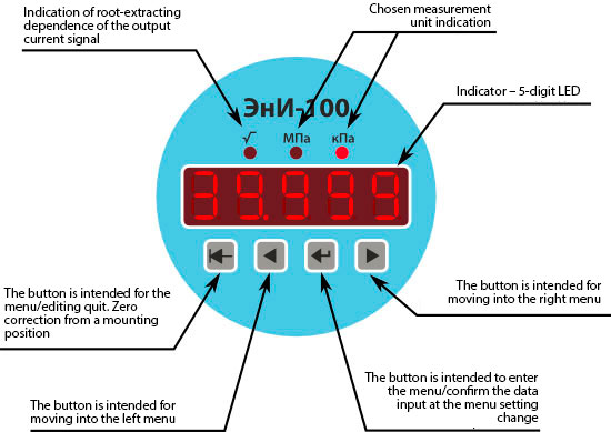
The indicator is installed into the electronic converter body frame in the gauges with version code MP3 (see the Table 14). In the pressure measurement mode the indicator displays the measured pressure value in the pre-set measurement units: kPa, MPa, mm of mercury, mmAq, kgf/cm2, kgf/m2, bar, Pa, warnings or diagnostic messages.

ЭнИ-100 adjustment is conducted for:

  • versions МП3 и МП3/ЖК — with the help of a built-in keyboard, with the application of a HART-communicator or HART-moden and computer;
  • versions МП2 — only with the application of a HART-communicator/HART-modem and computer.

Appearance of the front panel with led indication (version МП3)

External appearance of the front plate with LED indication (version МП3)

1 2 1

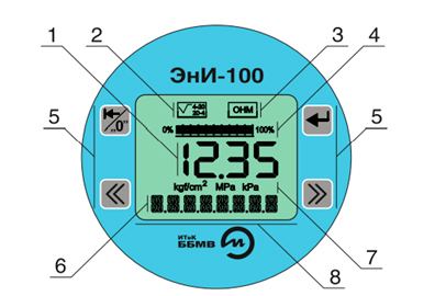
External appearance of the front plate with liquid-crystal indication (version МП3/ЖК)

1 — button "Exit"— button to exit menu / exit edit menu option. Correction of "zero" from the mounting position;
2 — button «Enter» — button-the button is used to enter the menu / confirm the data input when changing the settings in the pressure sensor menu;
3 — button «Left» — the button is intended for movement in the menu to the left;
4 — button «Rightwards» — the button is used to move the menu to the right;
5 — display zone based on the output current:

  • — «√»+«4-20» — root-out direct dependence;
  • — «√»+«20-4» — root-extracting inverse relationship;
  • — «4-20» — linear-increasing dependence;
  • — «20-4» — linear-decreasing dependence;

6 — status field — it is intended to indicate the presence of the following types of sensor configuration locks:

  • — «О» — lock changing settings from the keypad and HART Protocol;
  • — «Н» — lock change the settings for the HART Protocol;
  • — «М» — lock the correction of zero with a magnetic button;

7 — барограмма — display the current measured pressure value in relative value according to the set upper (100 %) and lower (0 %) limits of measurement;
8 — measured value — display the current measured pressure value in numerical form according to the set units;
9 — indication of the selected unit — the main units of pressure measurement that are most commonly used in the pressure sensors produced ЭнИ-100: kgf/cm2, Pa, kPa, MPa;
10 — text string — text string displays additional unit values that cannot be displayed in the Units field (for example, mm Hg). art., mm of water. kgf/m2, bar), also serves to display the menu of the pressure sensor, navigation through which is made using a four-button keyboard.

The gauge configuration menu allows one to set the value for upper and lower limits of pressure measurement, correct «нуль» from the installation position and static pressure, change measurement units, output signal conversion characteristics (linear or root-extracting), damping time, calibrate the gauge against the reference pressure, calibrate current output.

The data exchange with a converter through a HART-protocol allows gauge identification, output parameter configuration, reading the measured pressure value, output current and output signal in %, output current setting, analog output signal calibration.

The digital signal from the gauges ЭнИ-100 can be accepted and processed by any HART-device (HART-communicator or HART-modem and computer) supporting the HART-protocol.

There is an opportunity to correct «zero» with the help of external magnetic key.

Table 10
Electr.connection code. Protection degree according to GOST 14254 Version options Connection name Dimensions
C0 - - No cable entry -
С IP66 general ind.
-Ex, -К
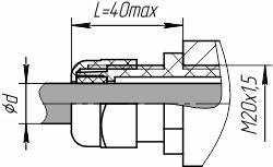
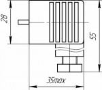
Cable (gland) enter the plastic cable Ø 6-11 mm, Lmax=55 mm  C, C1
С1 Cable gland, metal cable Ø 6-12 mm, Lmax=55 mm
ОК12 Cable gland for non-armoured cable general industrial purpose version, single seal d=6-12 mm  ОК12, ОК14, К12, К14
ОК14 d=6,5-14 мм
К12 general ind.
-Ex, -К , -Вн
Cable gland for non-armoured cable explosion-proof version Exd, single seal d=6-12 mm
К14 d=6,5-14 mm
2КБ12 Cableglands for armoured cables explosion-proof version EXd double seal for all types of armour/braiding d=6-12 mm, D=20max  2КБ12, 2КБ14,
2КБ14 d=6,5-14 mm, D=20max
К12М15 Cablegland for non-armoured cable for a metal hose РЗ-ЦХ and МРПИ d=6,5-12 mm, DN=15 mm  К12М15, К14М15, К14М18, К12М20, К14М20
К14М15 Cablegland for non-armoured cable for a metal hose РЗ-ЦХ d=6,5-14 mm, DN=15 мм
К14М18 Cablegland for non-armoured cable for a metal hose РЗ-ЦХ d=6,5-14 mm, DN=18 mm
К12М20 Cablegland for non-armoured cable for a metal hose РЗ-ЦХ and МРПИ d=6-12 mm, DN=20 mm
К14М20 Cablegland for non-armoured cable for a metal hose РЗ-ЦХ and МРПИ d=6,5-14 mm, DN=20 mm
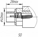
ШР14 IP65 general industrial purpose -Ex, -К  Plug connector: plug2РМ14    ШР14, ШР22
ШР22 Plug connector: plug 2РМ22
- Included with the ШР14: 2РМ14 socket and straight pipe with shielded nut
Included with the ШР22: 2РМ22 and the pipe line with shielded nut
GSP Plug GSP 3 Type A under DIN 43650  GSP
Socket GDM 3016 Type A under DIN 43650 - Sealing GDM 3  GSP
Table 11
Process connection code Installation parts Figure Applicability
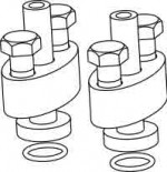
К1/4 male Mounting flange with a fitting, thread К1/4" 1 16 1 -ДД-2410, -ДД-2412, -ДД-2420, -ДД-2430, -ДД-2434,  -ДД-2440, -ДД-2444, -ДД-2450, -ДД-2460, -ДВ-2210 –ДВ-2212,  -ДВ-2220, -ДВ-2230,  -ДВ-2240, -ДИВ-2310, -ДИВ-2312,  -ДИВ-2320, -ДИВ-2330, -ДИВ-2340, -ДА-2020, -ДА-2030, -ДА-2040, -ДИ-2110, -ДИ-2112, -ДИ-2120, -ДИ-2130, -ДИ-2140, -ДИ-2159,-ДИ-2169
1/4NPT male Mounting flange with a fitting, thread 1/4"NPT
К1/2 male Mounting flange with a fitting, thread К1/2" 1 16 2
1/2NPT male Mounting flange with a fitting, thread 1/2"NPT
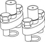
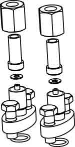
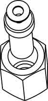
М20 Nipple with a union nut М20x1.5 for the connection along the external diameter of the pipe, 14 mm (with the installation via a mounting flange with a fitting, thread М20x1.5) Nipple of 12Х18Н10Т 1 16 3
М20У Carbon steel nipple
Н Nipple for the connection along the external diameter of the pipe, 14 mm (with the installation via a mounting flange) Nipple of 12Х18Н10Т 1 16 4
НУ Carbon steel nipple
К1/4 Mounting flange with a threaded connection К1/4" 1 16 5
1/4NPT Mounting flange with a threaded connection 1/4"NPT
К1/2 Mounting flange with a threaded connection К1/2" 1 16 6
1/2NPT Mounting flange with a threaded connection 1/2"NPT
М20 Nipple with a union nut M20x1.5 to connect along the external diameter of the pipe, 14 mm 1 16 7 -ДА-2040м, -ДА-2050м, -ДА-2051,  -ДА-2056, -ДА-2056м, -ДА-2060м, -ДА-2061, -ДИ-2140м, -ДИ-2150м, -ДИ-2151, -ДИ-2156, -ДИ-2156м, -ДИ-2160м, ДИ-2161, - ДВ-2231, -ДИВ-2340м, -ДИВ-2350м, -ДИВ-2351
Ф Connection flange to mount the gauge ЭнИ-100-ДГ on the reservoir wall
under GOST 33259-2015 (ver. 3 line 1, Ру=1,0 MPa, Dу=80 mm), paronite gasket ПОН under GOST 15180-86, fastening kit
1 16 8 -ДГ-2530, -ДГ-2540
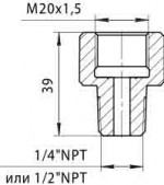
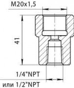
1/4NPT male. Adapter М20x1.5 for 1/4"NPT extern. 1 16 9 -ДА-2040м, -ДА-2050м, -ДА-2051, -ДА-2056, -ДА-2056м, -ДА-2060м, -ДА-2061, -ДИ-2140м, -ДИ-2150м, -ДИ-2151, -ДИ-2156, -ДИ-2156м, -ДИ-2160м, ДИ-2161, -ДИВ-2340м, -ДИВ-2350м, -ДИВ-2351
1/2NPT male. Adapter М20x1.5 for
1/2"NPT extern.
1/4NPT female. Adapter М20x1.5 for
1/4"NPT female.
1 16 10
1/2NPT female. Adapter М20x1.5 for
1/2"NPT female.

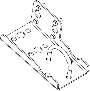
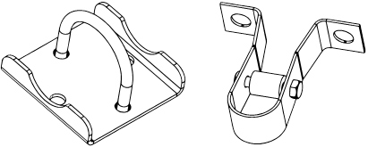
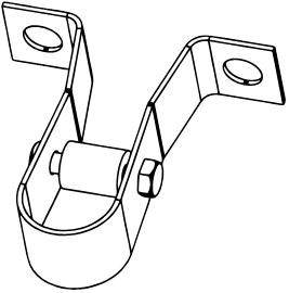
Mounting bracket

Table 12
Code Name Figure Applicability
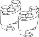
СК Clamp and bracket to fix the gauge on a pipe 1 17 1 -ДД-2410, -ДД-2412, -ДД-2420,-ДД-2430, -ДД-2434, -ДД-2440, -ДД-2444,-ДД-2450, -ДД-2460, -ДВ-2210, -ДВ-2212, -ДВ-2220,-ДВ-2230, -ДВ-2240, -ДИВ-2310, -ДИВ-2312, -ДИВ-2320,-ДИВ-2330, -ДИВ-2340, -ДА-2020, -ДА-2030, -ДА-2040,-ДИ-2110,-ДИ-2112, -ДИ-2120, -ДИ-2130, -ДИ-2140,-ДИ-2159, -ДИ-2169
1 17 2 -ДА-2040м, -ДА-2050м, -ДА-2051, -ДА-2056, -ДА-2056м, -ДА-2060м, -ДА-2061, -ДИ-2130м, -ДИ-2150м, -ДИ-2151, -ДИ-2156, -ДИ-2156м, -ДИ-2160м, ДИ-2161, -ДИВ-2340м, -ДИВ-2350м -ДИВ-2351
К3 Bracket to fix the gauge on a flat surface 1 17 3

Warranty liabilities

The manufacturer guarantees the gauge complies with TC 4212-010-59541470-2012 providing the customer follows the condition of transportation, storage, installation and operation.

Table 13
Parameter Value
Warranty operating life, months 36 months since the commissioning date but no more than 42 months since the date of manufacture

Комплект поставки

Table 14
Name Number
Gauge 1
Operation manual 1
Data Sheet 1
Calibration method 1
Socket 2РМТ (in compliance with the order) 1
Spare part kit (in compliance with the order) 1
Mounting bracket (in compliance with the order) 1

Designations at the order

ЭнИ-100-Вн-ДД 2440 02 МП3 t10 010 (0...160)kPa 25МПа 42 С М20 БКН СК К
1 2 3 4 5 6 7 8 9 10 11 12 13 14
  1. Gauge name as per the Table 4 ((tab 2).
  2. Gauge model as per the Table 4 (tab 2)
  3. Gauge version code according to materials in the Table 1 (tab 1).
  4. Gauge version as per the electronic converter optionprovided in the Table 9 (tab 4).
  5. Climatic category as per the Table 2 (tab 1).
  6. Code of the limit of permissible basic percentage error 5, 6 и 7 (tab 3).
  7. Adjusted measurement range as per the Table 1 (tab 2) from the range of standard values (non-standard range as agreed with the manufacturer) is given in measurement units.
  8. Maximum permissible operating excess pressure as per the Table 1 (tab 1)  ) (only for gauges ДД and ДГ), given with a measurement unit.
  9. Converter output signal сode as per the Table 3 (tab 1).
  10. Electric connection as per the Table 10 (tab 5).
  11. Process connection code (spare part kit) as per the Table 11 (tab 6).
  12. Code of valve block installation on the gauge. The valve block is indicates as a separate order line in compliance with the technical conditions ЭИ003-00.000ТУ. The variety of supplied valve blocks should be specified at the order or in the corresponding catalogue sections. The gauge data sheet contains a corresponding note on leak tests conduct.
  13. Mounting bracket СК as perTable 12 (tab 6).
  14. The version (indicated as -K) intended for the operation on a gaseous oxygen and oxygen-containing gas mixtures (not used for the versions —Вн и —Ex).

The codes 1-10 are mandatory to fill in at the order completion.

The examples of the gauge designation at the order and in the documents of other products where it can be applied.

  • • Pressure difference gauge ЭнИ-100-ПД, model 2440, with the materials contacting with a processing medium, 12Х18Н10Т and the membrane made from the material 36НХТЮ, with a microprocessor electronic HART-based converter with a built-in LED indicating device, extreme operation conditions from minus 40°С up to plus 80°С (version group S2 under GOST R52931), with a limit of basic percentage error ±0,1 % at the decrease of the upper measurement limit not more than 10 times, measurement range 0 - 160 кPa, limit permissible operating excess pressure 25 MPa, output analog signal 4-20 mA, cablegland (nylon) with an external diameter not more than 11 mm, two mounting flanges with male thread 1/2"NPT,, with the gauge-mounted block valve, bracket T to be mounted on the tube ∅50mm is identified as follows:
    ЭнИ-100-ДД-2440-02-МП3-t10-010-(0...160)кПа-25МПа-42-С-1/2NPT-БКН
    ТУ 4212-010-59541470-2012.
  • • Excess pressure gauge with an explosion-proof enclosure» ЭнИ-100-Вн-ДИ, model 2150м, with the materials contacting with operating media, 12Х18Н10Т and the membrane made from 36НХТЮ, alloy material with a microprocessor electronic HART-based converter without an indicating device, extreme operation conditions from plus 5°С up to plus 50°С (version group V3 under GOST R52931), with a limit of permissible basic percentage error ±0,25 % % at the decrease of the upper measurement limit not more than 10 times, measurement range 0 до 1,6 MPa, output analog signal 4-20 mA, cablegland for an armoured cable up to 12 mm, double seal for all types of armour/braiding is identified as follows:
    ЭнИ-100-Вн-ДИ-2150м-02-МП2-t1-025-(0...1,6)МПа-42-2КБ12
    ТУ 4212-010-59541470-2012.

Pressure gauge ЭнИ-100

Buy pressure sensors, pressure transducers ДИ, ДИВ, ДД, ДГ from the manufacturer. High quality at the best price. Import substitution
wait Item successfully added.
Proceed to checkout?
1000 characters left
Обработка персональных данных включает согласие с Пользовательским соглашением и Политикой конфиденциальности и Вы принимаете их условия.