Key technical characteristics
| Parameter |
Value |
Range of A.C. supply voltage range*, V
with the registration of the measurement result
without the registration of the measurement result |
120...265
85...265 |
| Consumed power, V·А |
not more than |
| ЧA.C. supply voltage frequency, Hz |
49,5...50,5 |
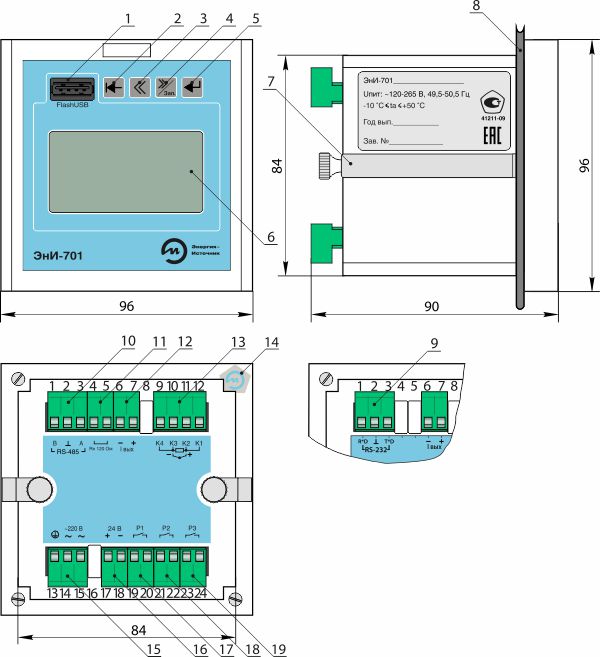
| Overall dimensions, mm |
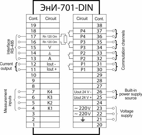
100x77x120 version DIN
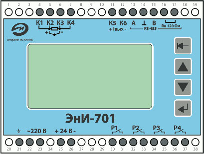
96x96x90 version 01 |
| Weight, kg |
0,4 |
| Structural design (by order) |
plastic body frame with a DIN or wall mounting option (version DIN)
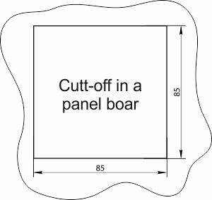
plastic body frame with a panel board-mounting option (version 01) |
| Calibration interval, year |
2 |
* * to provide the reliability or record and measurement results storage, at the decreasing of the supply voltage lower than 120 V the registration is blocked while the other registering device functions do not change.
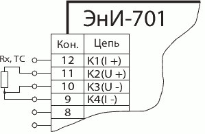
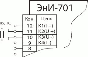
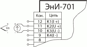
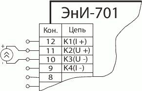
Measurement channel
The registering device also has one measurement channel.
The registering device measures signals:
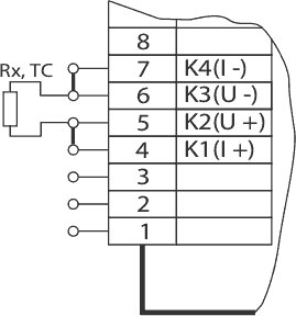
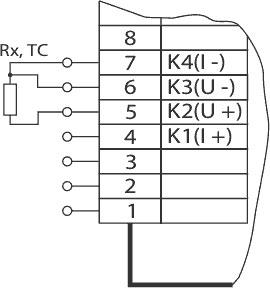
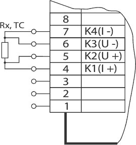
- from thermal converters (TC) with nominal static characteristics (NSC) in compliance with GOST 6651-2009;
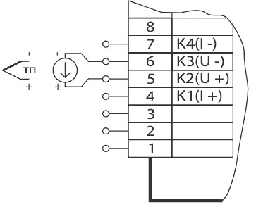
- from thermoelectric converters (thermal couples) (TC) having NSC in compliance with GOST R 8.585–2001
- D.C. voltages in the ranges 0...20 mV, 0...50 mV, 0...100 mV, 0...1 V;
- D.C. Intensity in the ranges 0...5 mA, 4...20 mA, 0...20 mA;
- resistances in the range 0...320 Om.
| Parameter |
Value |
| Number of measurement channels |
1 |
| Device input resistance at the connection of the unified current signal source, Om |
50 |
| Device input resistance at the connection of the unified voltage signal source, kOm |
not less than 100 |
| Connection diagram of thermal voltage converters (chosen by the user) |
2-х, 3-х, 4-wire |
| Length of the connection line of resistance thermal converters at the line resistance (RL≤15 Оm), m |
not more than 100 |
| Length of the connection line of thermal couples at the line resistance (thermal electrode cable) (RL≤100 Оm), m |
not more than 20 |
| Length of the connection line of the DC current unified signal at the line resistance (RL≤100 Оm), m |
not more than 100 |
| Length of the connection line of the DC voltage unified signal at the line resistance (RL≤5 Оm), m |
not more than 100 |
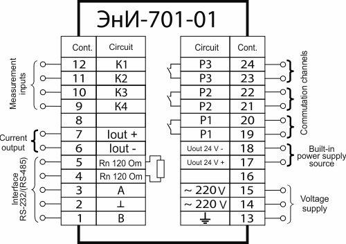
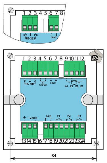
Current output
The registering device (by the order) has a current output channel forming a unified current signal within the ranges 0...5 mA, 0...20 mA, 4...20 mA. A current output channel can be used as a stable current source within the range 0...20 mA set to the accuracy 0,01 mA.
| Parameter |
Value |
| The functional dependence of the D.C. output signal value on the input measured parameter (adjusted by the user) |
linear, root-extracting |
| Limits of permissible basic percentage errors with a linear dependence |
see the Tables 3, 4, 5, 6, 7 |
| Limit of permissible basic percentage error pf root-extracting, % (at the measurement of D.C. intensity) |
± 0,1 |
| Current output load resistance for the range of output current 0...5 mА, Om |
not more than 1500 |
| Current output load resistance for the ranges of 4...20 mА, 0...20 mА, Om/td> |
not more than 400 |
| Limits of permissible complementary error of the current and digital outputs induced by the ambient temperature change from a normal value up to any temperature within the operation temperature range for every 10 °С |
not more than the limits of permissible basic percentage error |
| Limits of permissible complementary error of the current and digital outputs caused by high humidity action |
нnot more than the limits of permissible basic percentage error |
| Limits of permissible complementary error of current and digital outputs caused by the supply voltage change from the nominal value in the operating range, V |
not more than a 0,5 limit of permissible basic percentage error |
Data archivation
To store the values of the measured parameters, the registering device is equipped with a built-in non-volatile memory of not less than 2 Mb. The memory operates as a cyclic one rewriting new data in the archive beginning when the memory is full. The frequency of data registration in the archive is 1-60 sec (set by the user). The time period for archive storage at the archive period of 3 second is at least 30 days. Archive file reading can be conducted through interfaces RS-232 or RS-485 on the computer and a USB-flash card through the interface USB-Host(only for the version 01).
Built-in power supply source
The calibrator consists of the built-in stabilized DC power source (the output voltage is 5; 12; 24 V) with the overload and short circuit protection device and galvanically separated from other circuits.
| Parameter |
Value |
| Output voltage, V |
5; 12; 24 |
| Output voltage deviation, % |
not more than 0,2 |
| Output voltage pulsation amplitude, V |
not more than 0,1 |
|
Maximum load current, mA:
at the voltage 5; 12 V
at the 24 V
|
40
26
|
| Tripping event current, mA |
not more than 40 |
| Short circuit current, mA |
not more than 20 |
| Output voltage change induced by the ambient temperature change, % |
not more than 0,1 |
| Output voltage change caused by vibration, % |
not more than 0,2 |
Communication interfaces
By the order, the registering device RS-232 with the interfaces RS-232 or RS-485. The interfaces allow for the adjustment of the registering device with the help of a computer as well as archive file reading.
| Type |
Number |
Exchange rate range, bit/sec |
Protocol |
Cable length, m, not more |
| RS-232 |
1 |
2400...115200 |
MODBUS RTU |
10 |
| RS-485* |
1 |
2400...115200 |
MODBUS RTU |
1200 |
* for the operation as a terminating device there is a built-in load resistance of 120 Om.
By the customer’s order the registering device version 01 is completed by the interface USB-Host to record archive data on the USB-flash card
There is an opportunity to connect the registering device with the interface RS-485 directly to a PC through the USB interface with the help of a converter of interfaces ЭнИ-402 (RS-485 USB)(see the catalogue section «Interface converters»). Recommendations on Layout of Main RS-485.
Commutation channels
Depending on its version, a registering device may have up to four galvanically separated commutation channels of AC and DC circuits, Commutation is ensured via a relay, optical relay or optical bidirectional triode thyristor.
The commutation channels state (closed/open) depends on the preset values (trigger level, hysteresis and trigger logic), the measured parameter value and regulation law. The preset values and parameters of a registering device by the customer. The registering device operation logic enables PID- control.

")


